Mirror Layers for the Large Synoptic Survey Telescope in Chile
Mission of the Large Synoptic Survey Telescope
At present, a special ground-supported mirror telescope is being built on the summit of the Cerro Pachón in Chile, which is 2682 meters high. Even though its largest primary mirror is only 8.4 meters in diameter, and, therefore, not as large as those of the biggest observatories in the world, its wide-field viewing angle of 3.5 degrees is one of a kind. For comparison, the full moon, when looked at from Earth, covers a viewing angle of 0.5 degrees. This telescope will scan the entire visible sky of the southern hemisphere in just three days using the largest digital camera to date, with a diameter of 64 m and a resolution of 3.2 billion pixels. Therefore, the specialty of this telescope is the mapping of large areas of the sky in short time. It is, in other words, the super wide-angle version among the mirror telescopes.
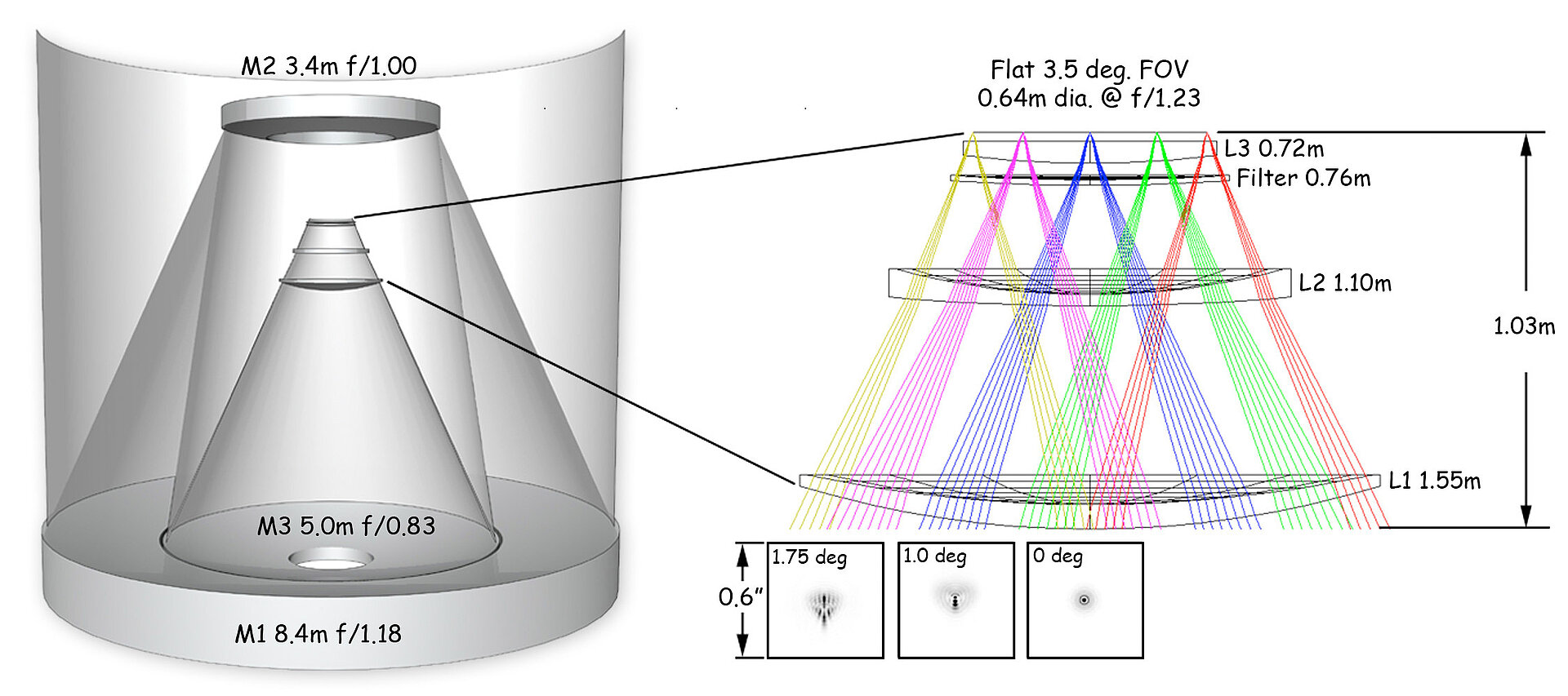
This is achieved by using an optical system with three mirrors (fig. 1). The primary mirror (M1) is ring-shaped, has a diameter of 8.4 meters and is made from a single piece. The tertiary mirror (M3) is integrated into the opening of the M1, has a diameter of 5 meters and a different curvature radius than the M1. Both mirrors form a monolithic structure that is referred to as M1M3 mirror. Above it, the secondary mirror is located (M2) with a diameter of 3.4 meters. This optical design enables a continuous overlapping image of 20,000 square meters of sky in six wavelength ranges between 32 and 1,062 nanometers.
With this observatory, at least ten billion stars and galaxies shall be catalogued. With a frequency of two complete images per week, even short-term events such as supernovae could be observed and asteroids that could get potentially dangerously close to the Earth could be identified.
Mirror coating
In order to maintain the optical characteristics that are necessary to operate the observatory, the mirrors, which are made of borosilicate glass, will be coated. This coating is based on silver and/or aluminum and will be made by means of magnetron sputtering (fig. 2). The layer system of the M1M2 mirror consists of an approx. 100 nanometers thin aluminum layer, which is protected by an approx. 8.5 nanometers thin silicon nitride layer.
For the smaller M2 mirror, a multilayer coating consisting of an adhesion layer of 6.5 nanometers thin nickel-chromium nitride, the actual reflection layer of 110 nanometers thin silver and a final protection layer of 8.5 nanometers thin silicon nitride. This silver layer has exceptionally good reflection properties in the visible and near infrared range. As the M2 mirror is directed downward and, therefore, better protected against the influences of the climate, its silver coating might last for several years. Thus, the light will be reflected, in sequence, by the aluminum layer of the M1 mirror, the silver layer of the M2 mirror and the aluminum layer of the M3 layer.
For these coatings, the proven recipes of the Gemini and SOAR telescopes will be used, which are located in direct vicinity on the Cerro Pachón under identical climatic conditions. The experience gathered there have shown that there are no major losses in reflectivity are to be expected for the silver-coated M2 mirror of the LSST over the years. The reflectivity of the secondary mirror of the Gimini South observatory, which is coated similarly, has remained the same since its initial coating in 2004. It has been cleaned on a regular basis with CO2. For the M3 mirror, it is estimated that the reflectivity will decrease by 1.5 % per year in the range of 450 nanometers and by only 0.025 % at 650 nanometers.
Operating regime
Standard CO2 cleaning is carried out every week for the M1M3 mirror and every second week for the M2 mirror. Due to the expected decrease in reflectivity described above, the M1M3 mirror should be recoated every two years in order to meet the very strict requirements for optical properties. The quality of the M2 mirror coating is assessed on the basis of the weekly measured reflectance values. The entire coating process for the M1M3 mirror, including transportation, can be completed within two working days.
This shows that the operating conditions here are unusual for a vacuum coating system. While very high availability and high throughput of the systems are usually the focus in industry, this mirror coating system must be reliably ready for operation immediately and deliver reproducible results, even after a long downtime.
Cleaning and coating station
Even if the mirror coating systems used are very stable for the prevailing climatic conditions, at least cyclical cleaning and occasional renewal of the coating is a mandatory requirement for stable and comparable measurement results within the investigation programs, which are designed to run for at least ten years. Due to the size and uniqueness of the mirrors and the exposed location, this can only be done on site.
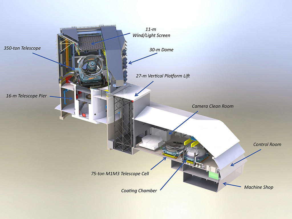
A hall area for cleaning and coating was therefore provided on the service floor of the observatory building complex (Fig. 3). This hall area consists of three interconnected segments: the cleaning and decoating area, the area of the coating system itself and a parking area for the lower part of the coating chamber.
The dimensions are based on the size of the M1M3 mirror with its 8.4 m outer diameter. Due to this size, the mirror cannot be transported individually, but is lowered out of the telescope together with its substructure using a platform lift. This cell assembly, which weighs around 55 tons, also serves as the lower part of the vacuum chamber and cannot be removed for cleaning the mirror.
The coating system works with the magnetron sputtering system already successfully used on other reflector telescopes (Gemini, VLT) to deposit the coatings. Von Ardenne GmbH was commissioned with the planning, construction and delivery of the entire system, consisting of cleaning, decoating and coating, and can thus contribute its many years of experience in glass coating and magnetron sputtering to the LSST project.
The cleaning section houses the washing arm, the inspection bridge and the perimeter platform for the M1M3 mirror as well as the decoating device for the M2 mirror. The functional areas of the coating chamber essentially consist of three segments.
Upper part of the coating chamber
This chamber area mainly contains the sputtering system. It has a total of eight radially arranged Von Ardenne Standard Single Magnetrons (SSM) with planar targets, with which aluminum, silver, nickel-chromium and silicon can be sputtered. For deposition in the reactive sputtering process, nitrogen, oxygen and krypton can be admitted directly to the magnetrons in addition to the working gas argon. The sputtering system can coat both rings of the M1M3 mirror simultaneously with the same material.
The magnetrons themselves are used in two sizes. The configuration used to coat the M1 mirror (SSM 11-41) has an effective sputter radius of 1.7 m with 1.9 m wide magnetrons and has a mask shape to adapt the coating rate to the radius of curvature of the M1 mirror. The M2 and M3 mirrors are coated with 2.4 m wide magnetrons (SSM 13-43) with an effective sputter radius of 2.0m. The 2.4 m wide units have two different, interchangeable masks that have been specially developed for the M3 and M2 curvatures.
Movable masks ensure that a homogeneous coating is applied at the overlap point with every overflow. The shape and movement of the masks must be very precisely matched to the geometry of the mirrors. The eight magnetrons are moved by two motors and rotate up to 540° above the mirror. All media for the magnetrons (electricity, cooling water, gas) and the control system are fed centrally via the main shaft, which is sealed on the vacuum side by means of a ferrofluidic rotary feedthrough.
The supply units for the magnetrons, such as gas flow regulators, pressure sensors, mask drives and water and gas distribution systems, are located in atmospherically pressurized containers above the magnetrons.
The upper section of the coating chamber is suspended from lifting jacks that can lift the total weight of the chamber of 140 tons and lower the upper section to its lower section in a precise position. One of the main challenges of the project was the absolutely safe design of the construction to protect the mirror from damage, as the majority of the components are mounted above the mirror surface.
Special design measures are necessary to prevent components from coming loose and falling off, as well as safety devices that reliably prevent contact with the mirror surface when the upper section is lowered. In addition, with such a large vacuum chamber, attention must also be paid to possible deformation of the chamber during pumping.
Another complicating factor is that the installation site of the system is located in an earthquake-prone area.
Intermediate ring
One of the challenges was that the M1M3 mirror had to be used with its own chamber substructure (cell), which, however, had to be decoupled from the actual coating area due to its insufficient vacuum suitability for the coating requirements. The function of this sealing system between the vacuum in the upper chamber and the vacuum in the lower chamber is performed by an inflatable seal on the inside of the intermediate ring.
This seal acts against the edge of the M1M3 mirror, giving it the function of a membrane between the two vacuum areas. To protect the mirror, pressure differences between the two areas must be excluded in principle in all operating states of the system. For this purpose, the sealing system has special safety and vacuum venting systems.
The system's fore-vacuum is generated by the proven combination of rotary vane and Roots pumps from Leybold GmbH. For the high vacuum in the lower chamber area, turbopumps from Pfeiffer Vacuum Technology AG are used in combination with screw pumps from Leybold. The final pressure in the range of 10-7 mbar required for the coating conditions is ensured by a combination of different cryogenic pumps, also from Leybold. The pump system is designed so that the backing pumps can evacuate the recipient to 2.7 - 10-2 mbar within one hour and the required outlet pressure of 3 - 10-7 mbar is reached within eight hours.
Lower part of the coating chamber
The lower part of the coating chamber is primarily used to keep the system under vacuum outside the coating campaigns and to accommodate the M2 mirror for coating. For the M1M3 combination, this chamber section is parked, as the M1M3 mirror cell is also designed as a vacuum chamber and therefore replaces the lower section.
Control system
The coating chamber is controlled by central software, which contains all the functions required for operation, such as the vacuum system, magnetrons, gas distribution, coating thickness sensors and in-situ camera monitoring. The controller also has an automatic mode and logs all coating parameters, including the status of each subsystem associated with each coating sequence.
Status
After a successful acceptance procedure including coating tests on dummy substrates that were made with the coating system, which had been fully assembled at the chamber manufacturer MAN in Deggendorf, Germany, at the time, the machine was dismantled and prepared for shipment. From Deggendorf, the entire machine was transported by ship to Antwerp in the Netherlands. From there, it was shipped to Chile where it arrived in October 2018.
The biggest challenge however was the overland shipment of the huge chamber halves from the harbor to the summit of the Cerro Pachón. As the cargo was nine meters wide, street lamps, road signs and overhead wires had to removed. Furthermore, the several linked towing vehicles had to move up a slope of 15 degrees.
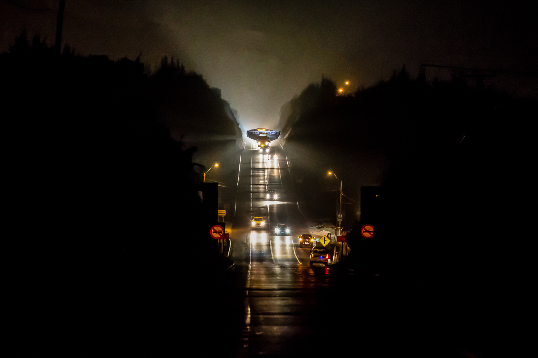
The most complicated bottleneck for all the components of the observatory was the passage through the Puclaro tunnel, not far away from the summit (fig. 7). Moving the cargo through it was precision work, especially for the two halves of the chamber, which are the largest components.
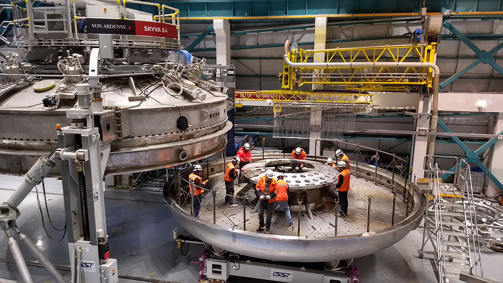
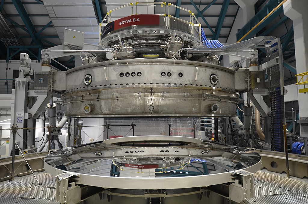
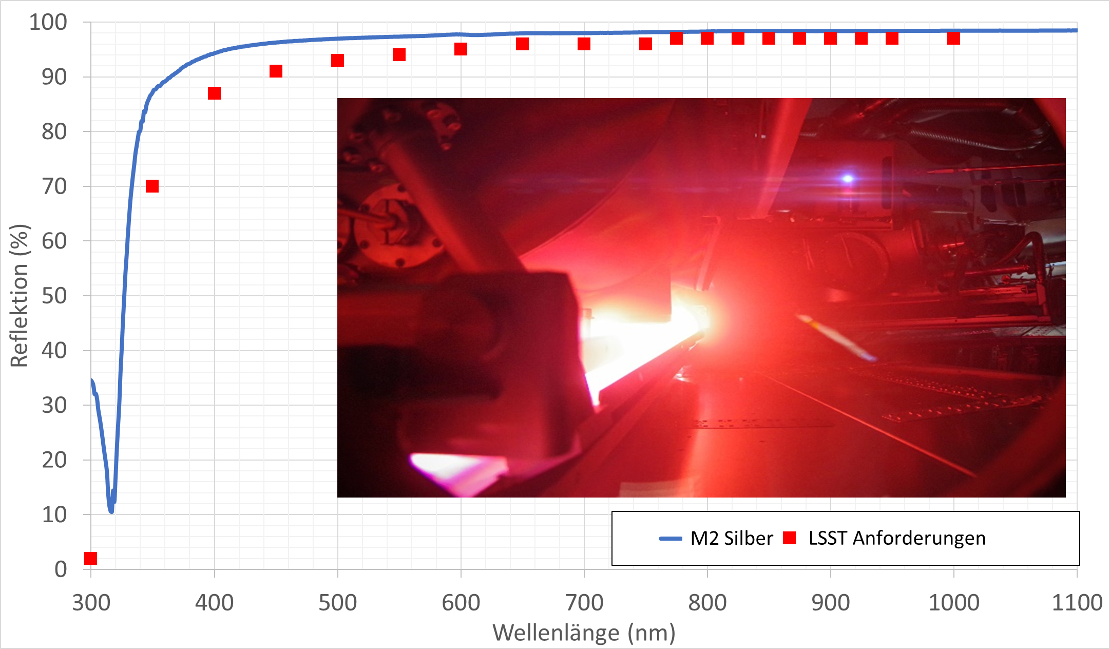
The assembly of the coating system began in January 2019 in the assembly halls of the observatory (fig. 8). In July 2019, the coating system mastered its first major challenge with the initial coating of the M2 mirror on site. The resulting reflectivity values surpassed those which had been specified (fig. 9).
Now, the machine is ready for the M1M3 mirror, which has arrived on the summit in the meantime. Thus, the way should be free for the completion of the telescope. In 2022, the first images of the stars shall be captured by this unique mirror telescope.
Sources
The article is primarily based on the following joint publication by the Association of Universities for Research in Astronomy (AURA) and VON ARDENNE GmbH.
Tomislav Vucina, Norman Müller, Bettina Michel, Markus Gehlert, Jörg Faber, Matthias Smolke, Torsten Wellner, Robert Künanz, Christian Melde, Heiko Naucke, Peter Espig, William Gressler, Jacques Sebag, John Andrew, and Doug Neil: „LSST coating plant status and progress“, Proc. SPIE 10700, Groundbased and Airborne Telescopes VII, 1070002 (Presented at SPIE Astronomical Telescopes + Instrumentation: June 10, 2018; Published: 6 July 2018).
The construction work and current status of the LSST are being documented extensively. Further information can be found here: https://www.lsst.org.
The figures 1,2,3,7 and 8 as well as the cover picture have been used with the consent of AURA, the source for the figures 4,5,6 and 9 is the VON ARDENNE Corporate Archive.
Authors
Norman Müller
Norman Müller was born in 1978 and holds a diploma in engineering. He has been working for VON ARDENNE since 2007 as a project manager for various large-scale projects. Currently, he is in charge of the cleaning and coating station for LSST at VON ARDENNE.
Ulf Seyfert
Mr. Seyfert was born in 1962 and wrote his doctorate at the TU Dresden on material science. He has been working for VON ARDENNE since 1998 in various positions in research and development. At present, he is responsible for research and development cooperation.
Figure 1: LSST ray optics with M1M3 combination (diameter of 8.4 meters or 5 meters, respectively, focal length 1.18 or 0.83, respectively), M2 miror (diameter 3.4 meters, focal length 1.00) and lens system of the camera (on the right, amplified view of lenses L1, L2 and L3). The field of view of the setup with a flat sensor array of 64 cm in diameter is 3.5°. The small rectangles show the point spread function (PSF) of the light sources.
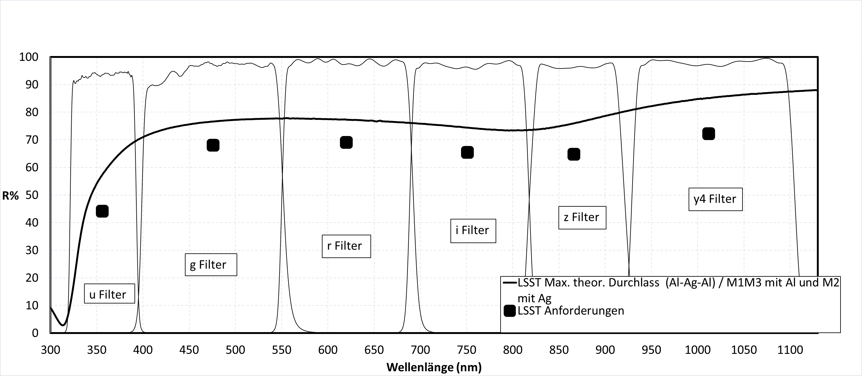
Figure 2: Expected reflectivity of the coated main mirrors (M1, M2, M3) for the usable wavelength range (filters in u, g, r, I, z and y4 band). The minimum reflectivity values necessary for the operation of the telescope (LSST requirement) are given for every filter element.
Figure 3: Layout of the observatory with the actual telescope, the service floor with the coating system and the connecting platform lift.
Figure 7: Precision work of transporting the chamber parts through the Puclaro tunnel.
Figure 8.1 and .2: Final assembly of the coating chambers (a) and the M2 mirror in the lower half of the chamber after successful initial coating (b).
Figure 9: Measured reflectivity curve of the M“ mirror (blue) with the specified required values (red); View through a viewport while magnetron is switched on (small picture).